PAS128 utility mapping, GPR, drainage and confined-space surveys — from a
desktop record search through to vacuum excavation, so the drawing you design from is one you
can build from.
Colour is the record. Four utilities, four colours, for the whole page.
01 — Before you dig
A utility drawing is a record of what someone believed was down there.
Records go out of date. Services get moved, added, abandoned and never redrawn;
drawings arrive in the wrong coordinate system, or with the last twenty years missing. PAS128
exists because of that gap — it sets out how a service is found on site, and how much confidence
the drawing that comes out of it actually carries.
a
The record is a starting point. A desk study tells you what should be there. It cannot
tell you where it is, or how deep.
b
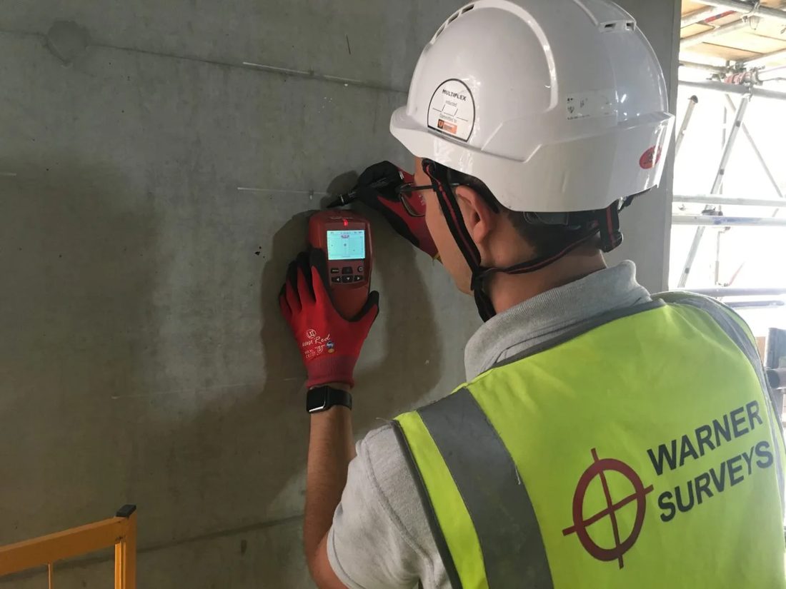
Detection is a measurement. GPR and electromagnetic location place the service on a
coordinate, tied in by GPS or total station.
c
Verification is proof. Where the level demands it, vacuum excavation exposes the
service and its position stops being an inference.
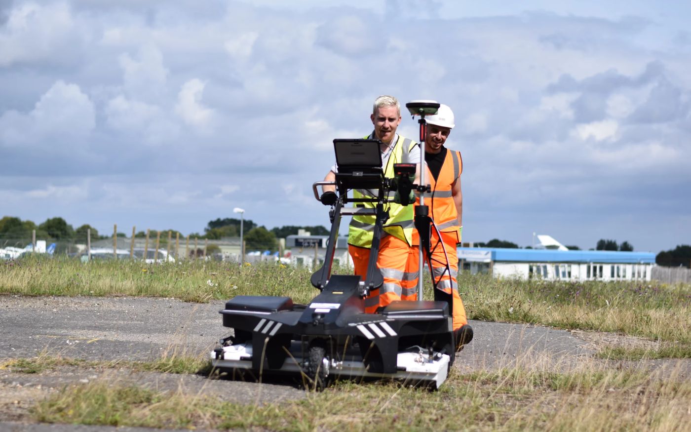
GPR on site — the array crosses a grid; the drawing is built from what
comes back.
02 — Schedule of services
Twelve services, in the order the work usually happens.
From a basic lift-and-dip of the manholes through to a high-specification
PAS128 survey — the whole chain is in-house, including the excavation that verifies it.
Schedule of services · Warner Surveys Utility Mapping Ltd
The design, marked on the ground where it will be built.
What comes back
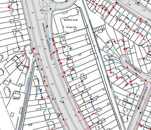
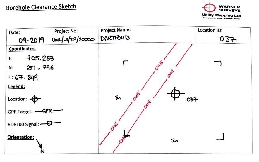
Two of the things the work produces. A plan sheet to design from, and a
clearance sketch to hand to a drilling rig.
Fig. 1 A utility plan sheet — services drawn over a
topographical base, each one tied to a coordinate.Fig. 2 A borehole clearance sketch — one location,
with the coordinates, the GPR target and the detected signal.
03 — PAS128 quality levels
Four levels. What changes is time on site — and what the drawing is worth.
PAS128 sets out four categories of survey, each weighing more time and effort
against more confidence in the result. You choose the level. We will tell you when a lower one
would do — and when it will not.
More time on site · more confidence
Less time on site · less confidence
A
Verification, including excavation
Detection, then proof. Trial holes or trenches — often opened by vacuum
excavation — expose the service so its position, depth and identity are confirmed on site. The
highest confidence the standard describes.
detected + exposed
B
Non-intrusive utility detection
Detection without excavation. GPR and electromagnetic location trace the service
and it is surveyed in. The position is measured; depth and identity rest on the response, not on
an open trench.
detected, not exposed
C
Site reconnaissance
Records, tested against the site. Chambers are lifted and dipped, covers and
markers are walked, and the drawing is corrected wherever the site disagrees with the paper.
records + walkover
D
Desktop utility record search
Records only — statutory authority drawings and any archived survey, compiled onto
one base. No site work at all, so it shows what is recorded rather than what is there.
records only
Not to scale. The four categories are ordinal: the
standard sets them out, and the depth of work in each is agreed with you before the survey starts.
Every level is delivered in-house, up to vacuum excavation of trial pits and trenches.
Specifying a survey?
The PAS128 discussion document walks through the options, so you can pick a
level rather than guess at one.
Half of this work happens in a chamber, not in a trench.
Drainage connectivity, CCTV and jetting all need someone at the bottom of a
manhole. Confined-space entry is its own competence — certified surveyors who can work inside a
chamber, culvert or deep manhole instead of photographing it from the top.
Confined space entry
Certified surveyors, entering the chambers and culverts that hold the actual connection.
Jetting, then CCTV
The drain cleared before it is filmed — a condition survey of the pipe, not of the silt.
Manholes and covers
Lifted and dipped, recorded, and tied back into the connectivity drawing.
Vacuum excavation
A trial hole opened without a machine bucket, so the service is exposed rather than struck.
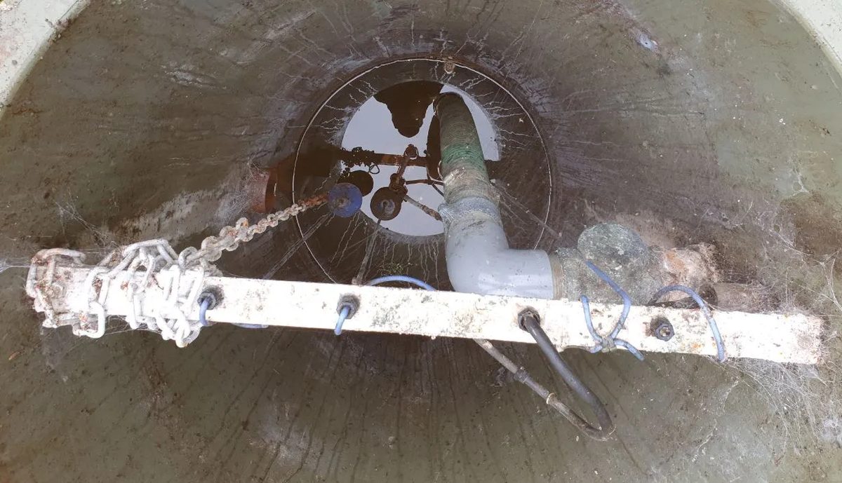
Chamber — a drainage connection, seen from the cover.
06 — Where we are
Five offices. The work runs nationwide.
Regionally based staff, so the crew that surveys your site is the one that can
come back to it — and the one that knows the local authority records.
Birmingham HQ
Unit 2 Regal Court, Kings Norton Business Centre, Kings Norton, Birmingham B30 3FJ
Send the drawing you have. We will tell you what level it needs.
A record drawing, an old survey, or nothing at all. Tell us what you are building
and when the ground opens, and we will tell you what has to be found before then.